This article is about establishing an LDP session across RSVP signaled LSPs and using those sessions to signal a Martini-draft style pseudowire.

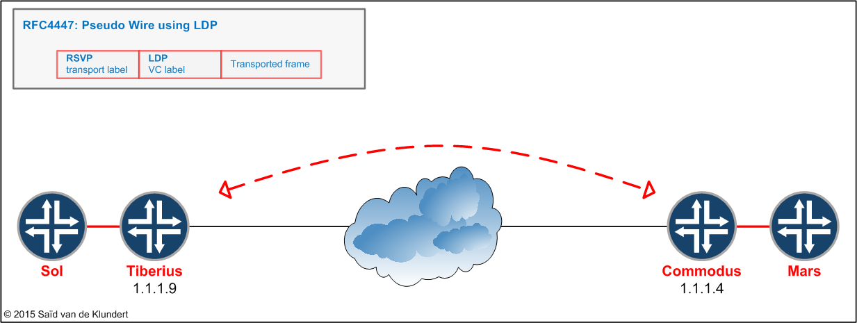
A way to provide layer 2 services to customers is to provide them with a Layer 2 circuit. This emulation of layer 2 services over an MPLS backbone is described in RFC 4447 ‘Pseudowire Setup and Maintenance Using the Label Distribution Protocol (LDP)’.
In this example, there is a customer who has two routers, Mars and Sol. These routers will have a direct layer 2 connection, by means of a pseudowire, across an MPLS network that separates them.

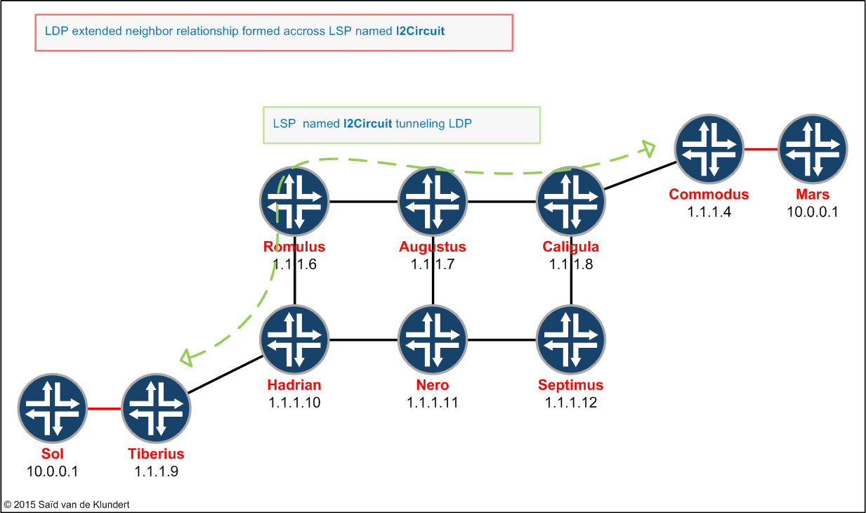
This pseudowire will be signaled using LDP. The two routers connected to the customer routers (Tiberius and Commodus) will form an extended LDP neighbor relationship with each other. Via this extended LDP neighbor relationship, the two PE routers will exchange VC-labels in order to create this circuit. There is no need to configure any VRF or route-distinguisher.
LDP will not be activated on all the routers in the network. The LDP control packets will be routed hop-by-hop, but the LSP established by LDP will make use of the RSVP established LSP.
To enable the LDP signaled pseudowire to make use of the RSVP LSP, we need to configure the RSVP signaled LSP with ´ldp-tunneling´. The following configuration commands will do just that;
Tiberius:
set protocols mpls label-switched-path lsp-to-Commodus-l2Circuit to 1.1.1.4
set protocols mpls label-switched-path lsp-to-Commodus-l2Circuit ldp-tunneling
Commodus:
set protocols mpls label-switched-path lsp-to-Tiberius-l2Circuit to 1.1.1.9
set protocols mpls label-switched-path lsp-to-Tiberius-l2Circuit ldp-tunneling
After enabling these LSPs between Tiberius and Commodus, we need to have both routers form an extended LDP neighbor relationship with each other. The following configuration will have the two routers form an extended LDP neighbor relationship with each other across an LSP:
Tiberius:
set protocols ldp interface lo0.9
set protocols ldp session 1.1.1.4 authentication-key "$9$RKySlMsYoDHms2JDikTQEcyrWx"
Commodus:
set protocols ldp interface lo0.4
set protocols ldp session 1.1.1.9 authentication-key "$9$87Z7dsiHmznCikfz36u0LxN-Yo"
The previous commands will enable LDP on the loopback interfaces of the PE-routers and instruct both routers to setup an LDP session with each other. After the LDP neighbor relationship is formed, the PE routers will be able to signal VC-labels to each other. To establish the pseudowire between Mars and Sol, we need to configure the l2circuit. Configuration wise, the l2circuit does not require a lot of effort. The customer facing interface need to have the proper encapsulation configured and the l2circuit needs to be configured under the [protocols l2circuit] stanza:
Tiberius:
set protocols l2circuit neighbor 1.1.1.4 interface xe-0/2/0.3556 virtual-circuit-id 3556

set interfaces xe-0/2/0 unit 3556 description Sol
set interfaces xe-0/2/0 unit 3556 encapsulation vlan-ccc
set interfaces xe-0/2/0 unit 3556 vlan-id 3556
Commodus:
set protocols l2circuit neighbor 1.1.1.9 interface xe-0/3/0.3556 virtual-circuit-id 3556

set interfaces xe-0/3/0 unit 3556 description Mars
set interfaces xe-0/3/0 unit 3556 encapsulation vlan-ccc
set interfaces xe-0/3/0 unit 3556 vlan-id 3556
Before delving into the control plane of the PE routers, let’s let’s verify that there is IP connectivity between the Mars and Sol router:
play@MX104-TEST-HB:Sol> show ospf neighbor
Address          Interface              State     ID               Pri  Dead
1.1.1.2          xe-2/0/0.3556          Full      10.0.0.2         128    37

play@MX104-TEST-HB:Sol> ping 10.0.0.2 source 10.0.0.1 size 1472 do-not-fragment
PING 10.0.0.2 (10.0.0.2): 1472 data bytes
1480 bytes from 10.0.0.2: icmp_seq=0 ttl=64 time=1.352 ms
1480 bytes from 10.0.0.2: icmp_seq=1 ttl=64 time=1.294 ms
^C
--- 10.0.0.2 ping statistics ---
2 packets transmitted, 2 packets received, 0% packet loss
round-trip min/avg/max/stddev = 1.294/1.323/1.352/0.029 ms
The previous commands show us that Sol and Mars have established an OSPF neighbor relationship and that there is IP connectivity between their loopback IP addresses.
Let’s see what we can verify on the PE and start by examining the l2circuit:
play@MX480-TEST:Tiberius> show l2circuit connections
Layer-2 Circuit Connections:

Legend for connection status (St)
EI -- encapsulation invalid      NP -- interface h/w not present
MM -- mtu mismatch               Dn -- down
EM -- encapsulation mismatch     VC-Dn -- Virtual circuit Down
CM -- control-word mismatch      Up -- operational
VM -- vlan id mismatch           CF -- Call admission control failure
OL -- no outgoing label          IB -- TDM incompatible bitrate
NC -- intf encaps not CCC/TCC    TM -- TDM misconfiguration
BK -- Backup Connection          ST -- Standby Connection
CB -- rcvd cell-bundle size bad  SP -- Static Pseudowire
LD -- local site signaled down   RS -- remote site standby
RD -- remote site signaled down  XX -- unknown

Legend for interface status
Up -- operational
Dn -- down
Neighbor: 1.1.1.4
    Interface                 Type  St     Time last up          # Up trans
    xe-0/2/0.3556(vc 3556)    rmt   Up     May  8 07:33:06 2015           1
      Remote PE: 1.1.1.4, Negotiated control-word: Yes (Null)
      Incoming label: 299776, Outgoing label: 299776
      Negotiated PW status TLV: No
      Local interface: xe-0/2/0.3556, Status: Up, Encapsulation: VLAN
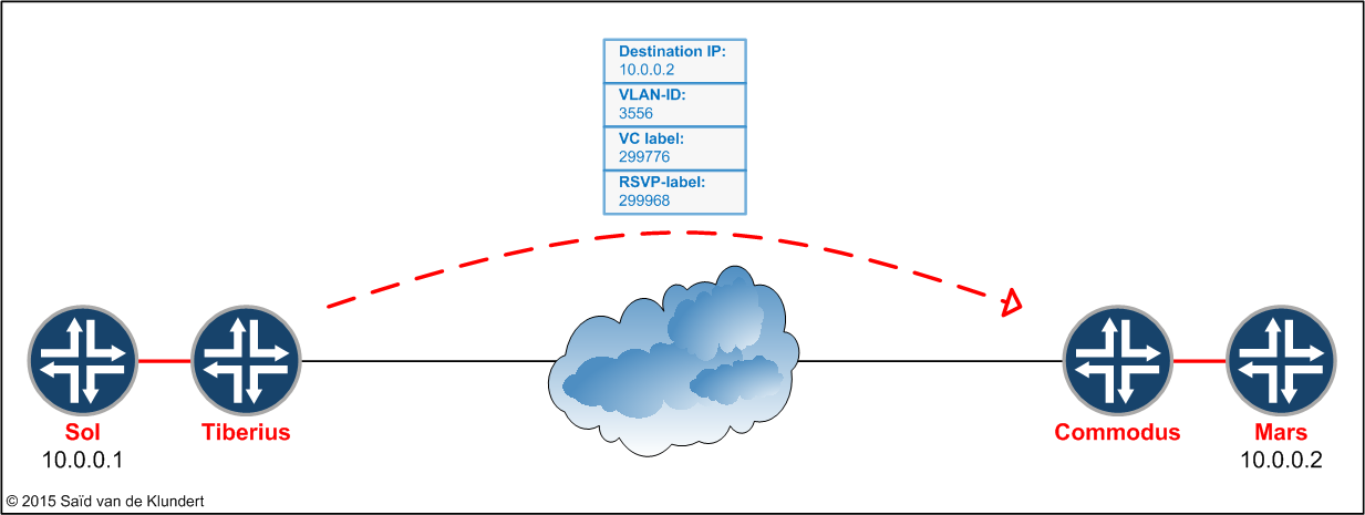
So the l2circuit is up and running and we have our first starting point in examining the control plane in a little more detail. The outgoing label that Tiberius will use, the label that Commodus signaled to Tiberius, is 299776. The label that is associated with a specific circuit can also be shown by issuing the ‘show ldp database’ command. You will see a ‘L2CKT CtrlWord’ entry in the database that indicates what label is associated with a VC:
play@MX480-TEST:Tiberius> show ldp database
Input label database, 1.1.1.9:0--1.1.1.4:0
  Label     Prefix
      ..           …
   …             ….
 299776      L2CKT CtrlWord VLAN VC 3556
Juniper MX also has a table called l2circuit.0. By consulting this table, we can get a more complete overview of the labels in use when traffic is send from Sol to Mars:
play@MX480-TEST:Tiberius> show route table l2circuit.0 detail

l2circuit.0: 2 destinations, 2 routes (2 active, 0 holddown, 0 hidden)
1.1.1.4:CtrlWord:4:3556:Local/96 (1 entry, 1 announced)
        *L2CKT  Preference: 7
                Next hop type: Indirect
                Address: 0x92f83ec
                Next-hop reference count: 1
                Next hop type: Router
                Next hop: 2.0.0.33 via xe-0/2/0.9 weight 0x1, selected
                Label-switched-path lsp-to-Commodus-l2Circuit
                Label operation: Push 299968
                Label TTL action: prop-ttl
                Session Id: 0x0
                Protocol next hop: 1.1.1.4
                Indirect next hop: 9430000 - INH Session ID: 0x0
                State: &<Active Int>
                Age: 2d 3:52:37         Metric2: 50
                Validation State: unverified
                Task: l2 circuit
                Announcement bits (1): 0-LDP
                AS path: I
                VC Label 299776, MTU 8978, VLAN ID 3556
This command shows the VC label and the LDP peer that signaled the connection. In addition, the printout also shows what LSP is used and what label corresponds to the LSP.
Just a moment ago, we send a ping from The Sol router towards the Mars router. This packet, send by Sol towards Mars, will have two labels attached. The previous command informs us on what labels the router is pushing onto the packet sent by Sol:

To verify that this RSVP label is indeed the label that is associated with the LSP ‘lsp-to-Commodus-l2Circuit’, we can issue the following command:
play@MX480-TEST:Tiberius> show rsvp session name lsp-to-Commodus-l2Circuit
Ingress RSVP: 2 sessions
To              From            State   Rt Style Labelin Labelout LSPname
1.1.1.4         1.1.1.9         Up       0  1 FF       -   299968 lsp-to-Commodus-l2Circuit
Total 1 displayed, Up 1, Down 0
Or another one:
play@MX480-TEST:Tiberius> show route protocol rsvp detail table inet.3

inet.3: 2 destinations, 4 routes (1 active, 0 holddown, 2 hidden)
1.1.1.4/32 (3 entries, 2 announced)
        State: &<FlashAll>
        *RSVP   Preference: 7/1
                Next hop type: Router
                Address: 0x92f877c
                Next-hop reference count: 9
                Next hop: 2.0.0.33 via xe-0/2/0.9 weight 0x1, selected
                Label-switched-path lsp-to-Commodus-l2Circuit
                Label operation: Push 299968
                Label TTL action: prop-ttl
                Session Id: 0x0
                State: &<Active Int>
                Age: 2d 3:44:39         Metric: 50
                Validation State: unverified
                Task: RSVP
                Announcement bits (1): 1-Resolve tree 1
                AS path: I
Anyway, the possibilities to examine how the Juniper MX is doing something often are endless.
Note that even though I did not clear any configuration from the previous lab, the l2circuit in this example follows the newly created LSP. The MX has multiple LSPs to reach the Commodus router:
play@MX480-TEST:Tiberius> show mpls lsp ingress
Ingress LSP: 2 sessions
To              From            State Rt P     ActivePath       LSPname
1.1.1.4         1.1.1.9         Up     0 *                      simple-lsp-to-Commodus
1.1.1.4         1.1.1.9         Up     0 *                      lsp-to-Commodus-l2Circuit
Total 2 displayed, Up 2, Down 0
But since the ‘lsp-to-Commodus-l2Circuit’ has been enabled to tunnel the LDP packets, this path is used to forward traffic that is send into the pseudowire. This fact can come in handy as it is one way to direct certain traffic, in this case l2circuit traffic, along a specific path with specific constraints (or specific CoS markers).
The configuration added to the Tiberius PE in this article:
set interfaces xe-0/2/0 unit 3556 description Sol
set interfaces xe-0/2/0 unit 3556 encapsulation vlan-ccc
set interfaces xe-0/2/0 unit 3556 vlan-id 3556

set protocols mpls label-switched-path lsp-to-Commodus-l2Circuit to 1.1.1.4
set protocols mpls label-switched-path lsp-to-Commodus-l2Circuit ldp-tunneling

set protocols ldp interface lo0.9
set protocols ldp session 1.1.1.4 authentication-key "$9$RKySlMsYoDHms2JDikTQEcyrWx"

set protocols l2circuit neighbor 1.1.1.4 interface xe-0/2/0.3556 virtual-circuit-id 3556
The configuration added to the Commodus PE in this article:
set interfaces xe-0/3/0 unit 3556 description Mars
set interfaces xe-0/3/0 unit 3556 encapsulation vlan-ccc
set interfaces xe-0/3/0 unit 3556 vlan-id 3556

set protocols mpls label-switched-path lsp-to-Tiberius-l2Circuit to 1.1.1.9
set protocols mpls label-switched-path lsp-to-Tiberius-l2Circuit ldp-tunneling

set protocols ldp interface lo0.4
set protocols ldp session 1.1.1.9 authentication-key "$9$87Z7dsiHmznCikfz36u0LxN-Yo"

set protocols l2circuit neighbor 1.1.1.9 interface xe-0/3/0.3556 virtual-circuit-id 3556