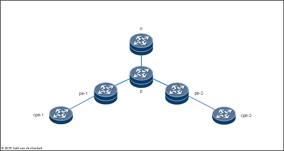
Normally, I use Huawei for all sorts of CPE stuff. But this time, instead of connecting a Huawei CPE to an MPLS VPN, I thought I’d use Huawei to create the Layer 3 MPLS VPN itself. Using eNSP, the free and open Enterprise Simulation Platform, I created the following scenario:

I began by configuring OSPF on the service provider routers. Here is the configuration from pe-1:
interface GigabitEthernet0/0/1
 ip address 10.0.0.5 255.255.255.252
 ospf network-type p2p
 ospf enable 1 area 0.0.0.0
#
interface LoopBack0
 ip address 10.0.0.252 255.255.255.255
 ospf enable 1 area 0.0.0.0
#
ospf 1
 area 0.0.0.0
#
After using ‘display ospf peer’ to verify the neighbor relationships, I proceeded to configure MPLS and LDP on the pe and p routers (it’s not required on the route-reflector). This has to be enabled globally on the router as well as on the interface level. On pe-1, the following configuration was required:
#
mpls lsr-id 10.0.0.252
mpls
#
mpls ldp
#
interface GigabitEthernet0/0/1
 mpls
 mpls ldp
#
LDP can be verified with ‘display mpls ldp peer’ or ‘display mpls ldp session’. To verify that the router has established LSPs towards the other routers in the network, you can use ‘display mpls lsp’.
After setting this up, I configured the pe routers to peer with the route-reflector like this:
bgp 65000
 peer 10.0.0.251 as-number 65000
 peer 10.0.0.251 connect-interface LoopBack0
 #
 ipv4-family unicast
  undo synchronization
  peer 10.0.0.251 enable
  peer 10.0.0.251 next-hop-local
 #
 ipv4-family vpnv4
  policy vpn-target
  peer 10.0.0.251 enable
The configuration to make the route-reflector peer with the pe-1 and pe-2 router was the following:
#
bgp 65000
 peer 10.0.0.252 as-number 65000
 peer 10.0.0.252 connect-interface LoopBack0
#
 ipv4-family unicast
  undo synchronization
  peer 10.0.0.252 enable
  peer 10.0.0.252 reflect-client
  peer 10.0.0.253 enable
  peer 10.0.0.253 reflect-client
 #
 ipv4-family vpnv4
  undo policy vpn-target
  peer 10.0.0.252 enable
  peer 10.0.0.252 reflect-client
  peer 10.0.0.253 enable
  peer 10.0.0.253 reflect-client
#
The vpn-target filtering is enabled by default on Huawei, so be sure to disable this on the route-reflector. To verify the BGP session, use the ‘display bgp peer 10.0.0.251 verbose’ command. This command will also show the configured address families.
Next was the configuration of the VPN itself:
ip vpn-instance ipvpn
 ipv4-family
  route-distinguisher 1:1
  vpn-target 1:1 export-extcommunity
  vpn-target 1:1 import-extcommunity
#
Placing interfaces into the VPN:
interface GigabitEthernet0/0/0
 ip binding vpn-instance ipvpn
 ip address 192.168.0.1 255.255.255.252
#
interface LoopBack1
 ip binding vpn-instance ipvpn
 ip address 192.168.1.2 255.255.255.255
#
The last stop was configuring the pe routers to distribute routing information for direct routes and to start a BGP session with the CPE:
bgp 65000
 #
 ipv4-family vpn-instance ipvpn
  import-route direct
  peer 192.168.0.2 as-number 65500
  peer 192.168.0.2 substitute-as
#
When reading ‘substitute-as’, think as-override.
After configuring the cpe-routers to peer with the pe-routers, the setup was complete. To verify that pe-1 is advertising and receiving routes:
<pe-1> display bgp vpnv4 all routing-table peer 10.0.0.251 received-routes


 BGP Local router ID is 10.0.0.5
 Status codes: * - valid, > - best, d - damped,
               h - history,  i - internal, s - suppressed, S - Stale
               Origin : i - IGP, e - EGP, ? - incomplete


 Total Number of Routes: 3

 Route Distinguisher: 1:1


      Network            NextHop        MED        LocPrf    PrefVal Path/Ogn

 *>i  0.0.0.0            10.0.0.253      0          100        0      65500i
 *>i  192.168.0.4/30     10.0.0.253      0          100        0      ?
 *>i  192.168.1.3/32     10.0.0.253      0          100        0      ?

<pe-1>display bgp vpnv4 all routing-table peer 10.0.0.251 advertised-routes

 BGP Local router ID is 10.0.0.5
 Status codes: * - valid, > - best, d - damped,
               h - history,  i - internal, s - suppressed, S - Stale
               Origin : i - IGP, e - EGP, ? - incomplete


 Total Number of Routes: 3

 Route Distinguisher: 1:1


      Network            NextHop        MED        LocPrf    PrefVal Path/Ogn

 *>   192.168.0.0/30     10.0.0.252      0          100        0      ?
 *>   192.168.1.2/32     10.0.0.252      0          100        0      ?
 *>   192.168.255.1/32   10.0.0.252      0          100        0      65500?
To verify connectivity between the loopback IP addresses of the CPE’s:

<cpe-1>ping -a 192.168.255.1 192.168.255.2
  PING 192.168.255.2: 56  data bytes, press CTRL_C to break
    Reply from 192.168.255.2: bytes=56 Sequence=1 ttl=252 time=50 ms
    Reply from 192.168.255.2: bytes=56 Sequence=2 ttl=252 time=50 ms
    Reply from 192.168.255.2: bytes=56 Sequence=3 ttl=252 time=40 ms
    Reply from 192.168.255.2: bytes=56 Sequence=4 ttl=252 time=50 ms
    Reply from 192.168.255.2: bytes=56 Sequence=5 ttl=252 time=50 ms

  --- 192.168.255.2 ping statistics ---
    5 packet(s) transmitted
    5 packet(s) received
    0.00% packet loss
    round-trip min/avg/max = 40/48/50 ms

<cpe-1>